Automatic bucket device design
Wu Xiping
In small and medium-sized barrel mills, steel drums before or after spraying are often transported by horizontal scrolling or chain horizontal dragging. However, in either form, the steel drum needs to be lifted or placed in the spraying process or in the warehouse. To solve this problem, we have designed and studied the automatic bucket device.
First, the motion analysis and structural form of the vertical barrel
First, we assume that the steel drum is conveyed by the angle steel carriage. Obviously, the horizontal rolling of the barrel is irregular. How to convert the horizontal rolling of the barrel into the established conveying, this is an important part of solving the process connection. What kind of mechanism is this specific process action solved? From the many drum cylinder forks on the production line, it is not difficult to get the association: Can the cylinder be used to drive the connecting rod, and then the connecting rod drives the fork to turn the steel barrel to stand up? The answer will be affirmative, but first the angle of the steel drum after standing up to the horizontal plane (or the angular displacement of the connecting rod around the O point θ) must be ensured. After analysis and observation, it is obvious that the angle α of the vertical barrel should be selected within the range of π/4<α<π/4. Because when α < π / 4, the barrel must be inverted; and when α > π / 2, the barrel has to go backwards, we can see that the angular displacement range we selected is correct. Figure 1.
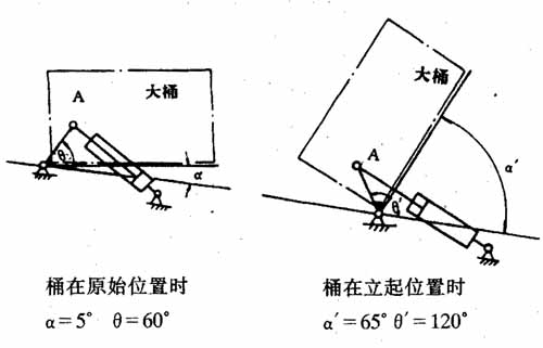
Figure 1 stand up angle
After the experiment, we chose the optimal angle of the vertical barrel α= 65°. In order to facilitate the barrel to maintain the upward movement in the fork, the fork can maintain the original inclination of 5° with the horizontal plane. From the structural point of view, we installed a connecting rod at the end of the fork shaft, that is, the connecting rod and the rotating shaft are fixed by a key. Since the two ends of the rotating shaft are supported by the rolling bearing housing, the connecting rod will rotate around the shaft center O under the push of the piston rod. The piston rod head is movably connected to the connecting rod head, and the tail of the cylinder rotates around the axis O' with the movement of the connecting rod. The entire cylinder will oscillate with the rotation of the O and O' axes, and this mechanism can essentially be regarded as a crank rocker mechanism. It can be seen from the figure that the motion trajectory of point A is the arc of the circle with O as the axis and the radius of the OA length. In fact, we want to get the constant velocity of the vertical barrel movement, that is, the first derivative of the angular displacement of the A point motion with respect to time; we also want to get the acceleration of the quick return fork in situ, that is, the angular displacement of the A point motion versus time. The second derivative, both of which are actually achieved, is determined by the form of the crank-rocking mechanism of the cylinder and the mounting form of the vertical barrel mechanism.
Second, the automatic control program design
Considering that the barrels that roll from the slide are often irregular and cannot be powered by external forces, the signal transmission can only be considered from the barrel itself. We have adopted gas-electric interlocking control, and the control principle is as follows:
As shown in Fig. 2, the control route will be like this: when the bucket is rolled into the semicircular fork, the contact disc 4 is pressed by the gravity of the bucket itself, and the small shaft together with the disc is inserted into the compression spring. In the hole, stretched out underneath. The spring and the small shaft are both installed in the steel pipe, and the steel pipe is fixed on the angle steel. Because of the small axial downward movement, the roller of the travel switch 5 is depressed, energized to cause the left end electromagnet 7 to suck and push the valve stem 10 to the right, so that the right end air å‘L is opened and the air is pushed to push the piston rod through the connecting rod and the rotating shaft. Drive the fork 1 to move the bucket up. When the connecting rod 2 moves to the required angle of the completed vertical barrel, the lower end of the connecting rod moves to the right to the roller of the travel switch 6, and the electric force is pressed to suck the right end electromagnet 9 to push the valve stem 10 to the left. The air hole at the left end of the valve body 9 is opened to supply air, the piston rod is returned to the original position, and the fork is returned to the original position. The contact disc 4 has now been reset by the spring, above the circular arc of the fork, in order to accept the cyclic movement of the next barrel.
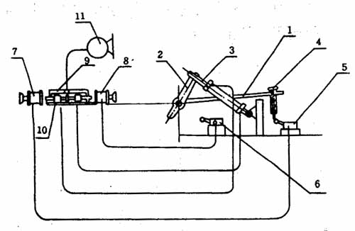
1-way fork; 2-link; 3-piston rod; 4-contact disc; 5, 6-stroke switch; 7, 8- traction electromagnet; 9-valve body; 10-valve;
Figure 2 gas system diagram
Third, the important actuator of the barrel - cylinder
According to the process characteristics of the vertical barrel, we chose a double-acting single-piston rod cylinder. Its structure is shown in Figure 3.
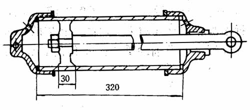
Cylinder stroke: L = 270mm; reciprocating time: t = 5s
Figure 3 cylinder structure
According to the actual measurement: the piston rod reciprocates once for 5 seconds, then the efficiency of the vertical barrel will be 12 barrels per minute, which is satisfactory according to the requirements of the general production line. When the cylinder is working, the thrust movement of the piston rod needs to overcome the frictional resistance and gravity to do work. In the return movement, it is only necessary to overcome the frictional resistance, and the gravity acceleration due to the weight of the fork makes us easily get a satisfactory fast return.
Fourth, the overall structure diagram
As can be seen from Fig. 4, in the mechanical installation, the vertical bucket fork is welded on the circular pipe material with the keyhole, and then integrated into a rotating shaft with the key, and the two ends are equipped with a rolling bearing box. A connecting rod with a key connection is installed at one end of the rotating shaft, and the force is stable due to the slow rotation speed, so it is safe and reliable. In addition, considering that the surface of the barrel is not affected by bumping, two steel pipes welded to the frame are mounted laterally in the lower right portion of the fork, and a compression spring is placed in the tube. When the barrel is rolled by the semi-circular fork, the collision of the pressure surface of the barrel reduces the collision between the surface of the barrel and the fork, and protects the surface of the barrel from damage.
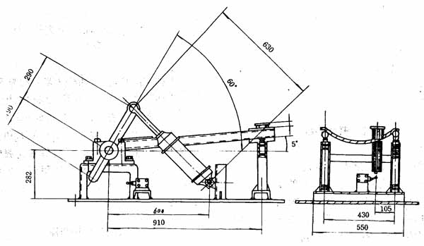
Figure 4 Schematic diagram of the overall structure of the automatic bucket device
V. Conclusion
In the process of designing the automatic bucket device, the determination of the two parameters often depends on the results of the experiment, but now I have carefully summarized it, but I have gained a deeper understanding of the theory. For example, when studying the thrust of the piston rod to point A, the magnitude of the required thrust varies from 50° to 65° depending on the angle at which the barrel stands up from standstill. Because the center of gravity of the barrel changes during the vertical barrel process. Obviously, the positive pressure W of the bucket to the shift fork (which can be regarded as a bevel) is G·COSαDX. The positive pressure W changes with the increase of α until the fork is dropped onto the chain conveyor. Therefore, the maximum positive pressure of the bucket on the fork is in the original position. Therefore, the maximum thrust of the cylinder is selected to be Fmax>F, and F is the initial maximum thrust of the curve A in the counterclockwise direction when the positive point of the connecting rod A is maximum, and the movement of the point A will be a curve arc motion. variable. The work done by force is A= ∫OF·X·COSαDX.
In summary, through the research and design of the automatic bucket device, our theoretical understanding and practical application have achieved satisfactory results.
Since its establishment, Baklam has always positioned product quality as the core of the company's participation in market competition. It is a professional dining table chair, dining room dining table chair, dining room dining table chair and dining room dining table chair customization manufacturer.
Dining table chair, dining room dining table chair, dining room dining table chair, dining room dining table chair customization, dining room dining table chair manufacturer
Baklam , https://www.baklamfurniture.com