Background of the project
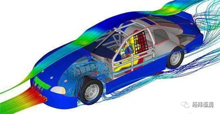
The project is a forward-looking study on automotive energy management using the TISC co-simulation tool by Rashad Mustafa of the Technical University of Braunschweig, Germany. Improve engine energy efficiency with engine package and intake grill active control technology.
When discussing the thermal management of a car, two conditions must be considered:
â— Longitudinal car dynamics model
â— Thermodynamic model of the power component (engine and wet dual clutch automatic transmission)
Project proposals
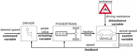
The longitudinal car dynamics model structure is shown in the following figure: the driver acts as a regulator, receives the required speed (command variable), and the regulator is generated taking into account the actual vehicle speed (control variable) and the value of the foot pedal at that time. variable). This action variable is transmitted to the power system and converted to a torque command that acts on the car.
The signal interaction between the models based on TISC is shown in the following figure:
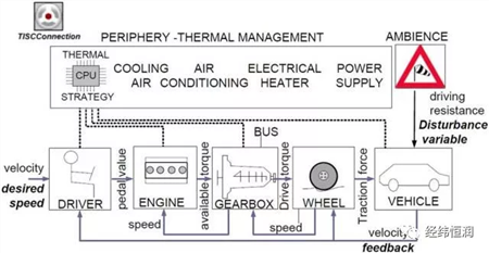
Traditional drive systems are divided into drivers, engines, wet dual clutch automatic transmissions, wheels, vehicles and perimeter models. The perimeter model contains the remaining necessary models, such as thermal management strategies, electrical systems, HVAC units, and fluid systems (oil, refrigerant, and air).
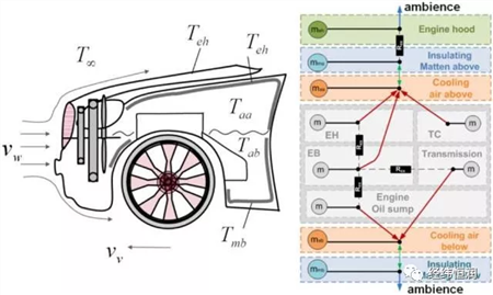
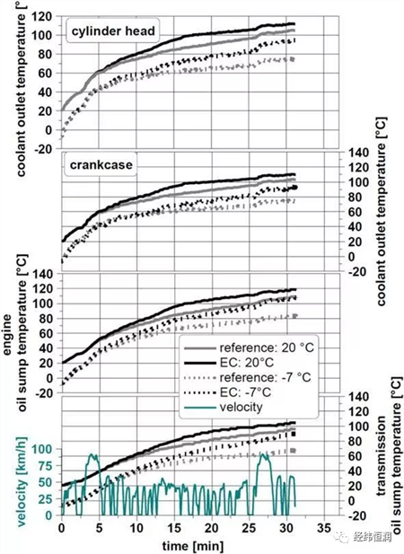
The actual temperature level actually present in the engine compartment is measured by the automotive hot wind tunnel test. To achieve this, eight temperature sensors are installed in the engine compartment. The figure below shows the different temperature levels in the cycle at room temperature of 20 °C.
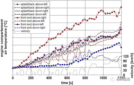
Based on the measured data, it is identified as two different temperature intervals. The low temperature zone is the part of the engine compartment component close to the floor and the high temperature zone is the top floor of the engine compartment. Therefore, the cooling air model needs to calculate two values. The heat transfer arrangement in the engine compartment is shown in the figure.
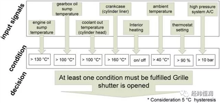
The control strategy of the intake grille is shown below:
Project effect
In this section, several driving cycles are simulated in this cycle, and the use of the cycle in operation is a high duty cycle and a low duty cycle. The NEDC and BS driving cycles represent European cities and country driving. The construction of the FIP-75 driving cycle is to describe the city driving in the United States.
Simulation results of the NEDC driving cycle
BS driving cycle simulation results
FIP-75 driving cycle simulation results
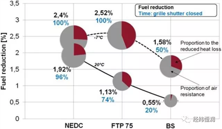
Fuel consumption comparison under three driving cycle conditions:
Project value
â— The thermal management system of the car can be optimized based on engine package and intake grill control technology. The optimization results depend on the location of the insulation and the grill valve
The key to the coupled model is to correctly characterize the signal transfer relationship between the equivalent masses.
â— The simulation model is a complex multidisciplinary model. Using the distributed simulation method, the simulation efficiency is improved and the simulation time is shortened while ensuring the simulation accuracy.
Sanitary Ware,Bathroom Sanitary Ware,Sanitary Item,Toilet Sanitary Ware
Hangzhou LvDong Building Materials Co., Ltd , https://www.ldunite.com