The lubrication circulation system not only acts as a lubricating mechanical structure, but also acts as a cooling and oil seal. Therefore, to ensure the purity of the oil, regularly clean the oil filter and piping to prevent blockage. If it is found that there is sediment in the oil bottle or the oil turns black, it is necessary to replace the new oil to avoid serious damage to the inside of the structure (gear joint, sliding shaft seal). Both the refrigeration system and the vacuum system use soapy water for leak detection. The method is: dissolve the soap with warm water, then add a few drops of glycerin, apply it to the preparation interface, and carefully observe whether there is gas trapping.
2. When the system is overhauled, the principle and operation procedure should be understood in detail. The mechanical structure diagram should be compared with the real object. Familiar with the position and function of all parts inside the instrument and the direction of the wire connection on the terminal block. The program checks step by step and gradually troubleshoots.
Common faults of this system are:
(1) The water pressure switch cannot be turned on. The reason is
1 contact poor contact
2 The bellows of the pressure switch is broken, the scale is blocked, the fatigue is long-term, or the mechanical components are loose.
(2) The oil pressure switch cannot be turned on for the following reasons;
A insufficient oil;
B oil circulation pump has failed;
C oil pressure switch is damaged;
D Contact contact is poor.
(3) The vacuum switch cannot be turned on for the following reasons;
A vacuum pump vacuum function is reduced;
B vacuum pressure is too low;
C vacuum system leakage;
D Contact contact is poor.
When the failure of the oil pressure switch, water pressure switch and vacuum pressure switch has not been determined, the pressure of the pressure spring cannot be adjusted at will. If you adjust the changes at will, the fault may be more expanded. If the pressure is raised, the technical indicators will not meet the requirements, the whole system can not be started, and the procedures for troubleshooting are added. If the pressure is lowered, the operating conditions of the instrument cannot be met, resulting in damage to other parts of the instrument. If it is determined that the pressure fault can be adjusted strictly according to the conditions required by the manual, such as the water pressure switch is 2 liter / minute flow, the vacuum switch is 8 × 10 ~ mmHg. If the contact is black due to excessive current, it will form irregularities or dirt, which will make the contact bad. It should be cleaned and trimmed in time. The blackened joints should be lightly polished with a bamboo bag E-deer skin, but the hammer or coarse sand paper is forbidden, as this will damage the protective layer of the joint, and the dirt can be cleaned with a sand cloth. Components that cannot be repaired must be replaced and cannot be used in order to prevent the expansion of the fault. In addition to the failure of each of the above pressure switches, abnormalities in the relay can also hinder the smoothness of the circuit. Frequent faults in relays;
A relay vibrates and does not suck well well;
There is no voltage at both ends of the B-line package. It is not good to open the relay contacts. First, check whether the voltage across the relay is normal. The terminal voltage cannot be lower than the rated value of 85. Under normal conditions, the vibration of the relay does not attract well. The reason is that the reaction force is greater than the suction force, and the reaction force depends on the reaction spring. The armature moves the frictional resistance. Therefore, attention should be paid to whether the shaft or other moving parts are stuck or not, so that the friction is increased. If this is not the case, the stroke can be reduced by adjusting the stroke screw of the relay if necessary. This is because as the stroke is reduced, the gap is also reduced, the resistance in the magnetic circuit is also reduced, the magnetic flux is correspondingly increased, and the suction force is also increased. It is also possible to reduce the spring pulling force of the reaction force, thereby reducing the reaction force. But be sure to disconnect the contacts when there is no voltage at both ends of the line package. Contact contact failure can be eliminated according to the above pressure switch contact processing method. The inspection of the instrument operating state control circuit can be carried out by referring to the circuit schematic attached to each centrifuge and the data given and the waveform of each point. Test instruments used in maintenance such as digital frequency meters, Nordic watches and multimeters should be accurate and reliable to avoid making false judgments. When welding parts and wires, the quality of the weld should be guaranteed. Flux oil can be used for flux and corrosive flux is not allowed. The electric ferrochrome used should have a suitable power. When soldering semiconductor components, the soldering temperature should be too high and the time should be too long to avoid damage to the components and the printed board copper foil.
(4) Common faults in the speed control part:
A instrument can't start, can't adjust speed and steady speed;
B Speed ​​up too fast:
C can not automatically stop when it is too fast;
D Do not deflate after low speed or shutdown.
The instrument cannot be started. Check that the indicator light is intact. If the indicator light is normal, the reason why it cannot be started is of course that the starting condition has not been met, and it should be checked step by step according to the driving conditions. First check that the positions of the knobs on the control panel are correct, and then check the start conditions one by one. Typical starting conditions include: the closed state of the door, the water pressure switch, the oil pressure switch, the vacuum in the centrifugal chamber, and the position of the timing controller. If the condition is still not activated, check the start control circuit, including the control line's insurance, power supply, voltage at each working point, and operating parameters of each component. The overspeed line is a differential amplifier with a fixed signal at one end and a feedback signal for the actual speed at the other end. Comparing the two, if the overspeed line loses control, the instrument will not operate normally. Usually, the original sleepy is the failure of the feedback signal generated by the actual speed or the components of the photoelectric speed measuring device and the control circuit. The control principle that the low speed cannot be deflated is also the differential amplifier, and the test is the same as that of Fan Guo. In addition, check whether the bleed valve and vent hole are unobstructed.
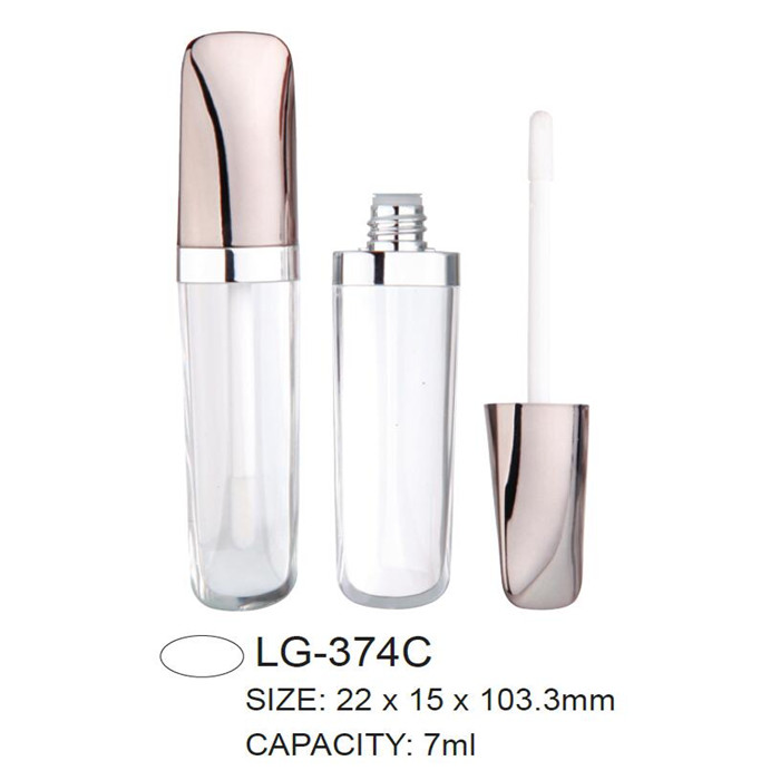
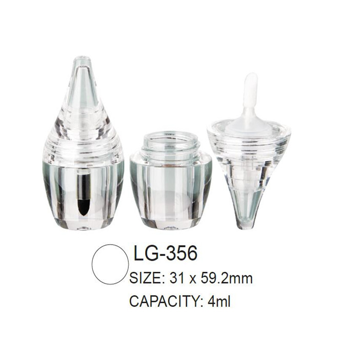
We have many different kinds of other shape Lip Gloss Case.Any injection color is avaliable for the empty plastic cosmetic lip gloss case.Spray painting/UV coating/metallized are also available for the lip gloss case.
|
MOQ |
12.000pcs |
|
Delivery time |
50-55days |
|
Material |
AS,ABS |
|
color |
Injection color,spray coating color,UV and metalizing color |
|
logo |
Silk screan and hot staping |
|
Packing |
paper carton |
|
Place of Origin |
Zhejiang |
We promise out standing service tailored to meet your demands. Our products are favored by many customers all over the world and are sold in Europe, North America, South America and Asia.
We are looking forward to your E-mail and establishing cooperative relationship with you! We would provide professional lip gloss case with good services for you.


Other Shape Lip Gloss Case, Odd Shaped Lip Gloss Tube, Lip Gloss Packaging
ims Packaging Limited , https://www.ims-cosmetic-packaging.com